Tool comparison
Find the best 3d splitter alternative for your model
The best 3d splitter alternative depends on whether you need a focused STL-splitting route or the editing control of Blender. Start with the file you have, the cuts you need, and the checks your printed parts must pass.
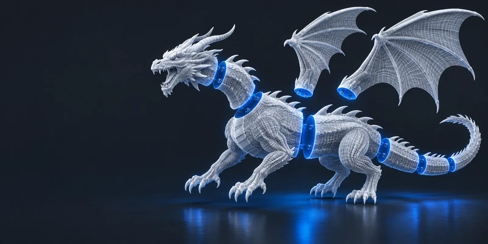
Verdict first: choose by the job
For an existing STL and a straightforward split, start with a dedicated STL tool. Choose Blender when the cut is part of a larger mesh-editing or assembly-design task.
- stl splitter online Compare what to check when your starting file is already an STL.
- how to split 3d model for printing blender Follow a Blender-oriented workflow when the mesh needs hands-on editing before printing.
- split 3d model for printing Plan cut placement around build volume, orientation, and the strength of the finished print.
Dimension by dimension: test the workflow
Rather than comparing labels such as easy or powerful, run the same model through three practical decisions.
-
1
Define the cut
Mark the intended seam and decide whether it only needs to divide an STL or must also hide inside the design. A 3d splitter route is worth considering for a direct separation task; Blender gives you room to reshape the seam, inspect geometry closely, and revise the surrounding mesh.
-
2
Check the resulting parts
Look for distinct, complete shells rather than assuming that a visible cut produces printable files. Inspect newly exposed faces and thin areas in a mesh editor or slicer. If the job calls for pins, sockets, or clearance between mating surfaces, plan those features separately instead of assuming a split creates them.
-
3
Test the print plan
Place each part in your slicer, check its orientation against the build plate, and preview supports and fragile features. The strongest 3d splitter alternative for your job is the one that leaves you with parts you can verify and assemble, not merely a model that looks divided on screen.
Who each option suits: a side-by-side comparison
The dedicated route here opens an STL splitter; Blender is a general-purpose 3D editor. The comparison separates the likely workflow from features you should verify yourself.
| 3dsplitter STL route | Blender | |
|---|---|---|
| Best starting point | You have an STL and want to investigate a focused splitting workflow. | You need to edit the mesh as well as divide it. |
| Scope of work | A route to a dedicated STL-splitting tool; confirm its available operations in the tool itself. | A broad 3D editing workspace with tools for mesh changes beyond splitting. |
| Custom cut geometry | Check the tool before relying on a particular cut shape or placement control. | Manual mesh editing allows you to design and revise more involved cut geometry. |
| Joining features | Do not assume it creates alignment pins, sockets, or assembly clearances. | You can model joining features, but you must design and check their dimensions. |
| Surface repair | Verify any repair capability separately and inspect the resulting shells. | Mesh editing and inspection tools can help you diagnose and repair problem areas. |
| Learning commitment | A focused route may be easier to evaluate for a single STL task, subject to the tool's actual interface. | A wider toolset takes more practice but supports more kinds of revision. |
| Print verification | Check every resulting part in a slicer. | Check every exported part in a slicer; editing control does not replace a print preview. |
Migration path: know what a tool switch cannot solve
Moving from Blender to a dedicated splitter can change the workflow, but it cannot replace decisions about geometry, fit, or physical printing.
It cannot choose a strong seam for you
A convenient cut can cross a load-bearing wall, a visible face, or an area that needs a clean assembly edge. A 3d splitter alternative does not remove the need to judge where the finished object should separate.
What to do instead
Sketch the seam on the model first, then review the cut against print orientation and expected forces.
It cannot guarantee watertight results
Existing holes, intersecting surfaces, and newly exposed cut faces can cause trouble when parts reach a slicer. Do not treat a visual preview as a mesh validation report.
What to do instead
Inspect each part individually and repair any open or non-manifold areas before printing.
It cannot make mating parts fit automatically
Two surfaces that meet exactly in a digital model may bind after printing. Pins, sockets, and tolerances are assembly-design choices, not an automatic consequence of dividing an STL.
What to do instead
Add joining geometry in a suitable editor and test a small sample joint before a full print.
It cannot preserve every aspect of an editable project
An STL is a mesh, not a complete record of a Blender project's modifiers, materials, or construction history. Switching routes to split an STL will not restore that source information.
What to do instead
Keep the original editable project and export a separate working copy for splitting.
Migration path: compare the model before and after
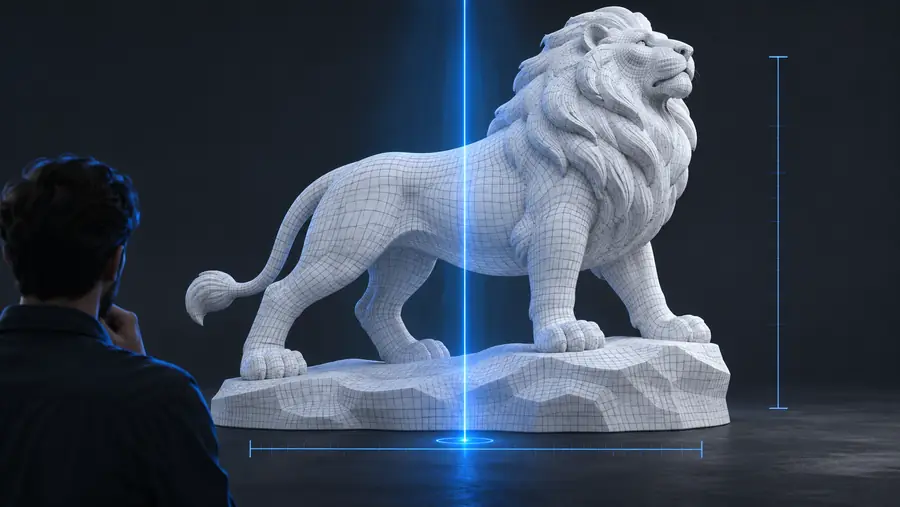
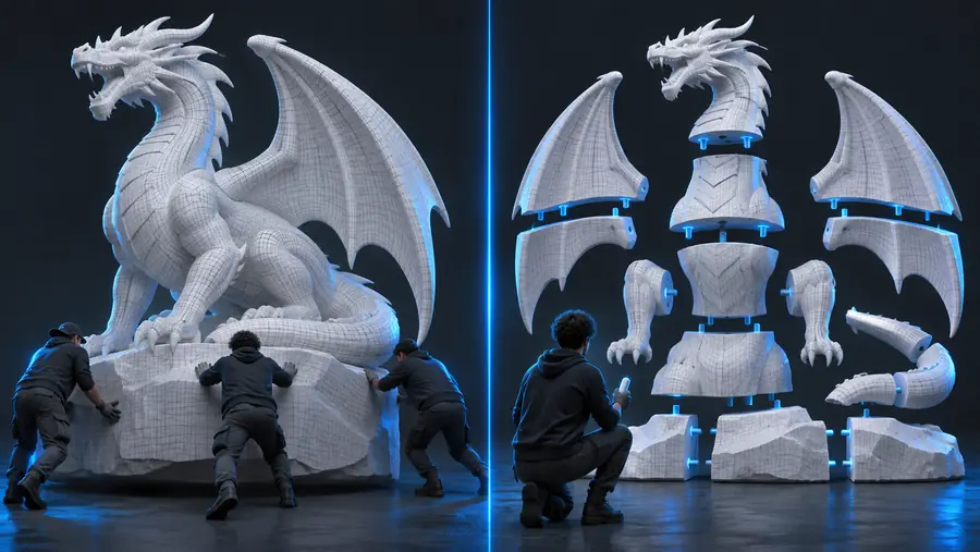
These are illustrative images, not screenshots or proof of a specific tool's output. When switching workflows, retain the original model, create a working copy, and compare each resulting shell with the intended seam. Then inspect the parts in a slicer before deciding whether the new route meets your needs.
Original modelPlanned separate partsMigration path: try the focused route
If your main task is separating an existing STL, open the dedicated tool and check whether its available split controls match your intended cut. Keep Blender in your workflow when you need to reshape surfaces, add joints, or repair the mesh. Whichever route you choose, validate the individual parts before committing to a print.
Start with the STL you need to divide
- Keep an untouched copy of the source file
- Check cut surfaces and separate shells
- Preview every part in a slicer
Comparison FAQ
If you already have an STL and mainly need to divide it, a dedicated STL-splitting route is a reasonable option to evaluate. If you also need to redesign the seam, add joints, or repair complex geometry, Blender offers a wider editing workspace. Compare the actual results on your model rather than assuming either route will handle every mesh.
Neither choice makes a model printable by itself. A dedicated route may suit a narrow splitting task, while Blender is more appropriate when the pieces need substantial mesh work. In both cases, inspect the shells and run a slicer preview before printing.
You can keep an STL as the working file when evaluating different splitting workflows, but check the destination tool's current input requirements before relying on it. Save the original separately so you can return to it if a cut needs revision. An STL will not carry Blender's full editable project history.
Do not assume a splitting tool creates pins, sockets, or the clearance they need. Review the tool's actual capabilities if those features matter to your project. Otherwise, design the joint in a mesh editor and print a small fit test.
Use a copy of the same source STL and aim for the same seam in each workflow. Check whether each resulting piece is separate, complete, and suitable for your build volume. Finally, compare cut surfaces and slicer previews, not just how quickly you produced a visible split.