Practical print scenarios
Where best 3d splitter examples fit a print workflow
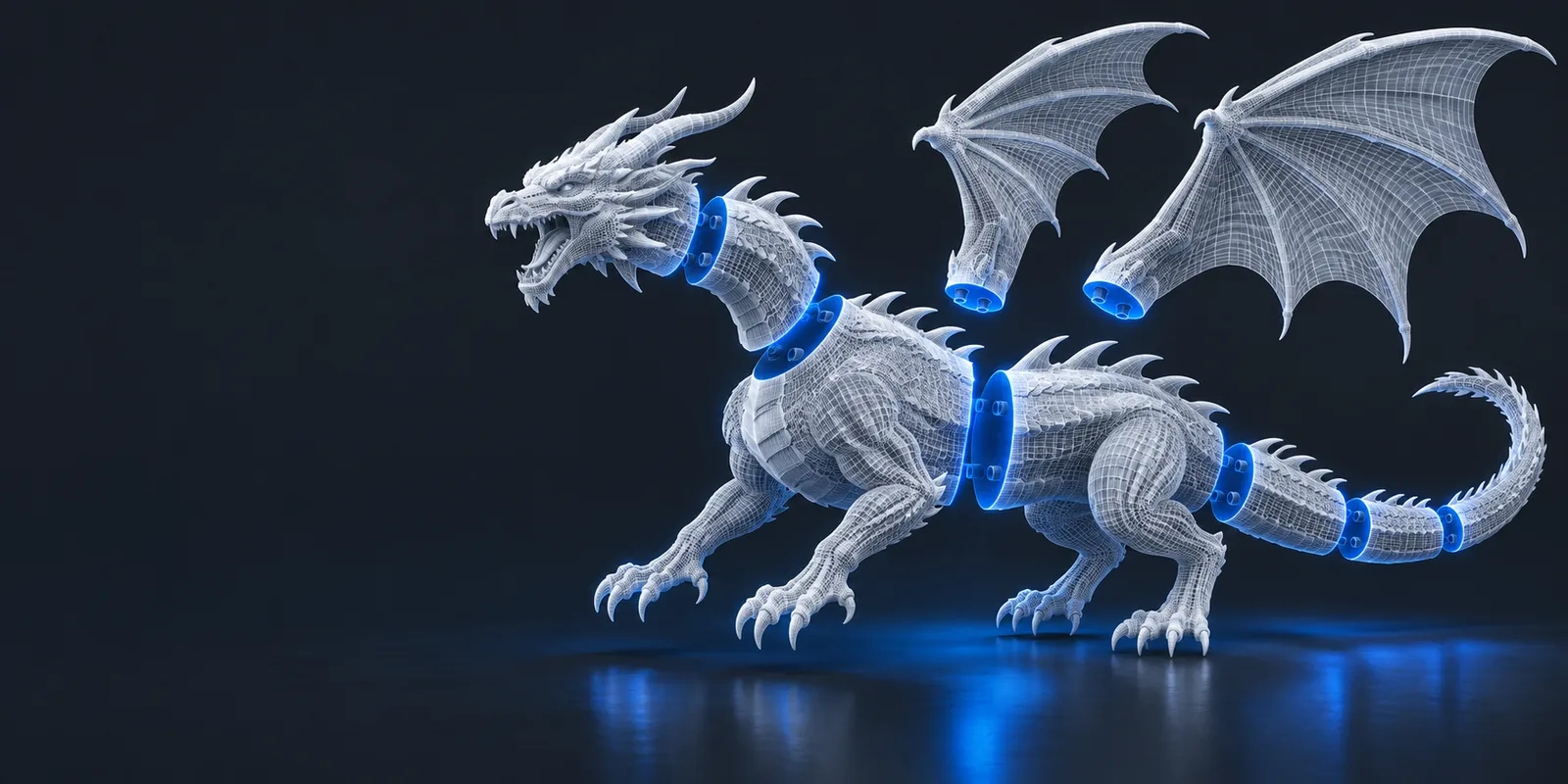
The best 3d splitter examples start with a reason to divide a model: it exceeds the build area, needs a different print orientation, or should be assembled from replaceable pieces. Use these scenarios to plan cuts and check the resulting parts before printing.
the audience's existing pipeline
Most projects begin with a finished model, not a cut. The useful question is what the printer or assembly needs that the intact model cannot provide.
- split 3d model for printing Plan part boundaries around build volume, orientation, and assembly.
- split stl into parts online Follow an STL-focused workflow for preparing separate pieces.
- split 3d model into parts by color Understand why color boundaries and geometry boundaries need separate planning.
where we slot in
A 3d splitter belongs between model preparation and slicing. It helps you evaluate part boundaries; it does not replace the checks needed for printable pieces.
-
1
Choose the constraint
For an oversized enclosure, identify the dimension that exceeds the printer's build area. For a figurine, find a seam that can be hidden or assembled cleanly.
-
2
Plan the division
Place candidate cuts where each piece can be oriented sensibly. Leave room for any alignment features or fastening method you intend to add in a modeling tool.
-
3
Inspect every piece
Check the separated geometry for open surfaces, unexpectedly thin walls, and tiny fragments. Import each intended piece into a slicer before committing to a print.
before/after
A useful before-and-after comparison asks whether the divided model solves the original constraint without creating a harder printing or assembly problem.
A cut cannot design a joint
Separating a shell does not automatically provide pins, sockets, screw bosses, or the clearance an assembly needs.
What to do instead
Model the connection deliberately, then test-fit a small section before printing the complete parts.
Separate geometry is not guaranteed printable geometry
A new boundary may expose holes, produce thin edges, or leave a fragment too small to handle reliably.
What to do instead
Inspect each part in a mesh checker and slicer; repair the geometry or move the cut when necessary.
Color is not always a physical boundary
A painted region or material assignment may not correspond to a distinct solid that can be separated cleanly.
What to do instead
Check the underlying mesh and create the required geometry in a modeling application.
deliverable spec
These examples compare the original model with the result you should be trying to prepare. They describe planning goals, not guaranteed output from a particular tool.
| Original model | Planned parts | |
|---|---|---|
| Oversized enclosure | One shell exceeds the build area in its intended orientation. | Pieces are sized for the available printer, with an accessible assembly seam. |
| Figurine | One mesh combines delicate details and surfaces that may need supports. | Parts have considered orientations and seams placed away from prominent details. |
| Repairable bracket | A damaged feature is built into a larger assembly. | The replaceable section has a defined attachment method and adequate strength. |
| Wall thickness | The intact mesh may conceal thin areas near a proposed cut. | Each cut edge is checked against the intended material and print process. |
| Fit | No joining clearance is needed while the model remains whole. | Mating surfaces account for printer tolerance and are tested before a full print. |
| Validation | Only the complete model has been reviewed. | Every intended piece is inspected separately in the slicer. |
Check a candidate split
Pick the example closest to your project and decide what the cut must accomplish before changing the mesh. The 3d splitter workflow is one step in that process; check fit, geometry, and print orientation afterward.
Start with the part boundary, then verify the parts
- Keep the original model
- Inspect each separated piece
- Test the assembly fit
scenario FAQ
A good example has a clear constraint and a way to judge the result. An oversized enclosure is useful because you can compare each planned piece with the printer's build area and check whether the assembly seam remains practical.
Start with the oversized enclosure scenario, even if your model is a different shape. Identify the dimension that does not fit, then consider cuts that produce printable orientations and manageable assembly surfaces.
A physical split can help when the colors correspond to distinct pieces you intend to assemble. Color information alone does not establish a clean geometric boundary, so inspect the mesh before choosing that approach.
Decide on the joining method while planning the cut so there is enough space for it. You may need a modeling tool to create connectors and clearance, followed by a small test print to verify the fit.
Check each piece for closed geometry, usable wall thickness, a suitable orientation, and support requirements in your slicer. If the pieces must fit together, test the mating surfaces before printing the entire assembly.