Printer owner
A prop extends beyond the available build area.
Plan sections that fit the bed, then check each part’s orientation and joining edges.
STL workflow
To split STL into parts online, start with the pieces you need and where the cuts should fall. A 3d splitter can help separate a model, but each resulting piece still needs inspection before printing.
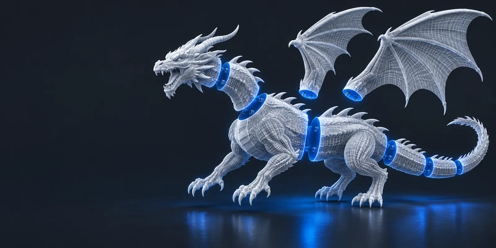
An STL stores a model’s surface geometry. Splitting it means turning the intended sections into distinct pieces that you can inspect and prepare individually.
A split is useful when the whole model is awkward to print, paint, or assemble. Choose the cut for the job, not just the shortest path through the mesh.
A prop extends beyond the available build area.
Plan sections that fit the bed, then check each part’s orientation and joining edges.
An arm blocks access to details on the torso.
Separate the arm to make painting easier while preserving a clear assembly position.
A curved seam must follow a specific feature.
Use a controlled editing workflow if a simple cut would damage that feature.
An STL may already contain disconnected shells.
Inspect the existing geometry before deciding whether another cut is needed.
Use the linked STL tool to examine its available splitting options. The exact controls and export choices depend on the tool.
Identify disconnected shells, thin walls, and the surfaces that must meet after assembly. Repair obvious mesh problems before making a cut.
Place the intended boundary where parts can print and join cleanly. Check whether the tool offers the type of split your model needs.
Inspect each part for open edges, missing faces, scale changes, and fit. Check the available export options before preparing the pieces for slicing.
Input: an STL surface mesh. Intended result: distinct model pieces. Verify boundaries, scale, and printability rather than assuming a split makes the mesh ready to slice.
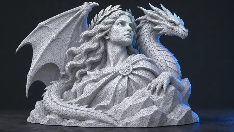
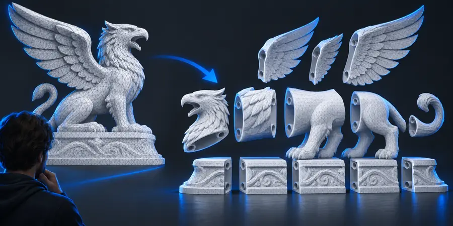
These images illustrate the workflow, not a verified output from the linked tool. A 3d splitter may separate geometry without repairing open surfaces or adding alignment features.
Before: inspect the whole meshAfter: check each intended pieceSeparating geometry is only one part of preparing an STL for printing. Review these limits before relying on an online split.
Two separated surfaces may not align or leave room for adhesive, pins, or tolerances.
What to do instead
Test the joint in a mesh editor and print a small fit sample when accuracy matters.
A cut can expose holes or non-manifold edges, especially in an STL that already has defects.
What to do instead
Run a mesh inspection and repair each resulting piece before slicing.
STL does not reliably carry the color assignments or design history needed to recover intended material boundaries.
What to do instead
Use the source project or a format that retains the information if color-based separation is essential.
Open the linked tool to see which separation options suit your STL. Once the pieces are distinct, inspect their surfaces and fit before sending them to a slicer.
An online STL tool may let you separate a model in a browser, depending on its available controls. Check the linked tool’s current options before assuming it supports the cut or export you need.
Not necessarily. Inspect each resulting mesh for holes, thin walls, and non-manifold edges, then check its orientation and fit in your slicer.
Some splitting workflows distinguish disconnected shells from a cut through connected geometry. Inspect the STL first so you can choose the appropriate operation rather than cutting a shell that is already separate.
An STL generally does not preserve reliable color boundaries for that purpose. If the intended sections came from a colored source model, use the original project or a format that retains those assignments.
Check that each piece retained the intended scale and that its joining surfaces still match. Then inspect the meshes for open edges and confirm that every piece fits your printer’s build area.