Painted miniature maker
A preview shows a red cloak and a gray figure, but the exported STL contains one continuous shell.
The colors do not define a cut. Create the cloak boundary in a model editor first, then inspect the separate parts.
Color-based splitting
To split 3d model into parts by color, first identify the boundaries between colors, then make sure the geometry can actually separate there. A 3d splitter can help divide an STL, but it cannot recover color information that the file does not contain.
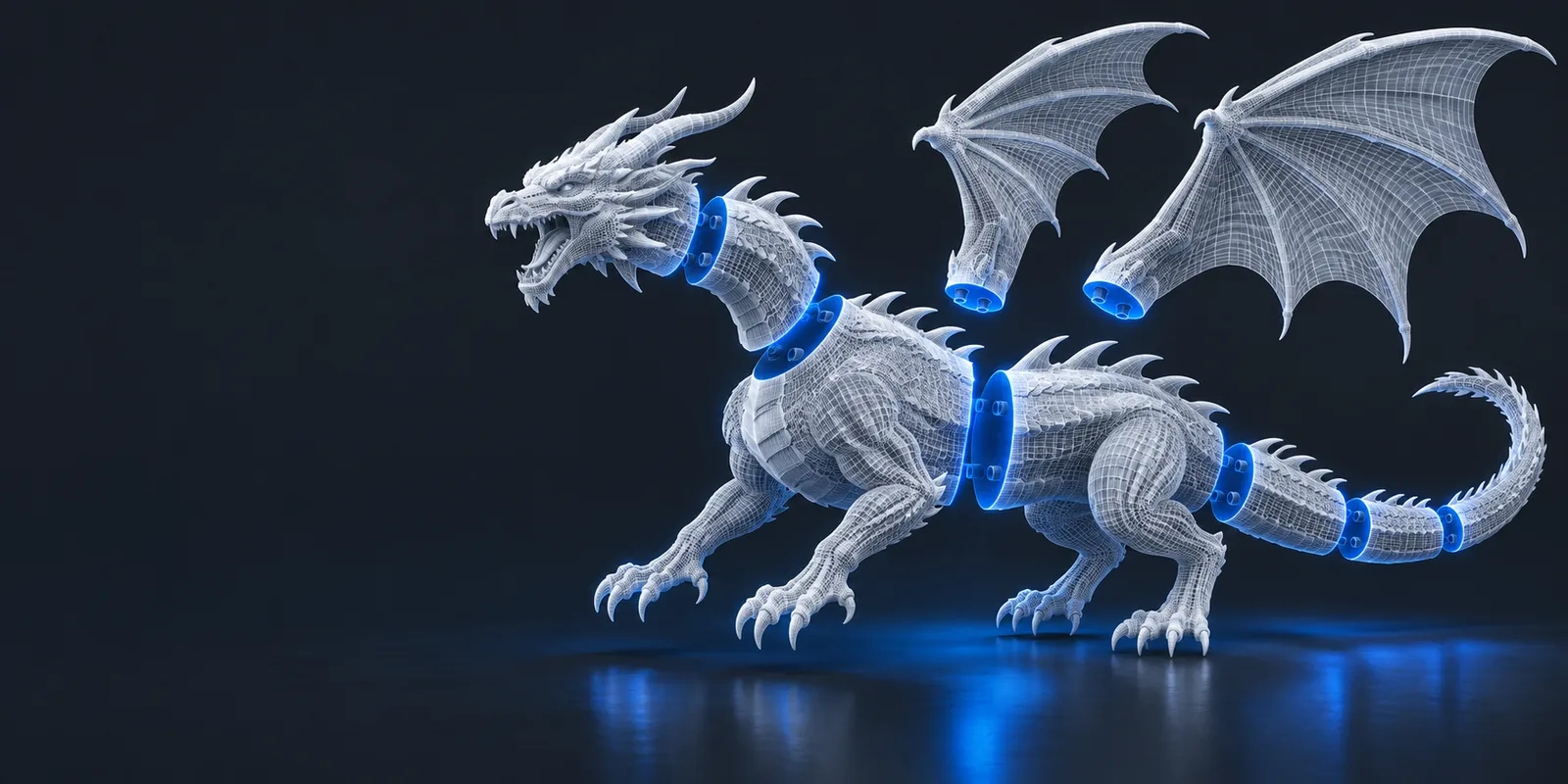
Color is a useful way to decide where parts should meet. It is not, by itself, a cutting instruction for an STL. Choose the workflow that matches the geometry you have.
A color-planned workflow adds decisions that a general 3d splitter workflow does not make for you. These steps describe preparation, not automatic color detection.
Identify which visible surfaces belong to each finished piece. Trace the boundary on the model rather than assuming a painted appearance represents separate geometry.
Decide whether the pieces need a flat mating face, a hidden seam, or room for an assembly feature. Keep the joint accessible for printing and finishing.
Inspect each resulting part for gaps, thin walls, and unintended fragments. A clean color boundary is useful only if both pieces remain suitable for the intended print.
Check what your source file contains before opening a 3d splitter. The distinction below determines whether you can proceed to a cut or need to edit the model first.
| Color-planned separation | General STL split | |
|---|---|---|
| Starting point | A model with visually distinct intended regions. | An STL that needs division into smaller pieces. |
| First check | Determine whether colors correspond to separate meshes, material assignments, or only a rendered appearance. | Inspect the shape and choose a feasible cut location. |
| Boundary decision | Place the seam where the finished color change should occur. | Place the cut for size, orientation, or assembly. |
| File preparation | Create separable geometry at the chosen boundary if it does not exist. | Prepare a valid mesh for the intended split. |
| What an STL retains | Surface geometry, not a dependable record of visible color regions. | Surface geometry for evaluating and dividing the shape. |
| Before printing | Inspect each piece and plan the color or material assignment separately. | Inspect each piece, its orientation, and its mating surfaces. |
A 3d splitter works with the geometry you provide. These common situations show when an STL cut is a useful next step and when preparation matters more.
A preview shows a red cloak and a gray figure, but the exported STL contains one continuous shell.
The colors do not define a cut. Create the cloak boundary in a model editor first, then inspect the separate parts.
A helmet shell and visor are already separate meshes, and the visor needs its own finish.
Check the meshes and their mating edges before exporting printable pieces.
A logo changes color across a broad flat face, but the source has no seam at its outline.
Model the outline and allow for assembly; a straight cut through the whole object may not follow the design.
The model exceeds the intended build area, while its color regions cross several possible cuts.
Prioritize fit and sound joints, then decide whether the resulting pieces can still be finished in the intended colors.
Once your intended seam exists as workable geometry, use the 3d splitter to assess the cut. Review the resulting pieces before treating them as print-ready: neither a visible color change nor a successful cut guarantees sound walls or a good joint.
A conventional STL describes a surface mesh, not reliable color regions that a splitter can follow. If the colors appear only in a preview or another source file, create the intended boundary in a modeling tool before exporting the pieces.
Inspect the source model’s object or mesh structure rather than relying on its appearance. If selecting one colored area also selects the entire shape, the visual boundary may not be a separable part.
A straight cut follows its cutting plane, not the outline of a design. For an irregular boundary, edit the geometry to form the desired seam and inspect the resulting mating surfaces.
Do not rely on STL files to carry the color assignments from a source model. Keep a reference to the intended finish and assign colors or materials through the workflow you use after splitting.